-- 发布时间:3/17/2009 8:08:00 AM
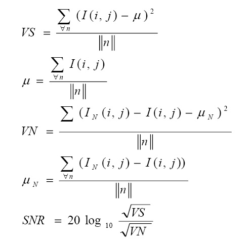
-- 如何計算SNR (signal-to-ratio)? (.NET) (C/C++) (C++/CLI) (GDI+) (Image Processing)
SNR公式如下
1
/**//*
2(C)
3
4Filename : SNR.cpp
5Compiler : Visual C++ 8.0 / C++/CLI
6Description : Demo how to compute SNR
7Release : 12/20/2006 1.0
8*/
9#include "stdafx.h"
10#include <iostream>
11#include <cmath>
12
13using namespace System::Drawing;
14using namespace System::Drawing::Imaging;
15using namespace std;
16
17// Convert RGB to gray level int
18int colorToInt(Color);
19
20// Calculate signal to ratio
21double SNR(Bitmap^, Bitmap^);
22
23int main() {
24 // Read lena.jpg
25 Bitmap^ oriImg = gcnew Bitmap("lena.jpg");
26 // Declare Gaussian image for lena.jpg
27 Bitmap^ noiseImg = gcnew Bitmap("lena_gaussian.jpg");
28
29 double snr = SNR(oriImg, noiseImg);
30
31 cout << "SNR of image:" << snr << endl;
32
33 return 0;
34}
35
36// Convert RGB to gray level int
37int colorToInt(Color color) {
38 return (color.R + color.G + color.B) / 3;
39}
40
41
42// Calculate signal to ratio
43double SNR(Bitmap^ oriImg, Bitmap^ noiseImg) {
44
45 // ||n||
46 int n = oriImg->Height * oriImg->Width;
47
48 // compute mean of signal
49 double sumU = 0.0;
50 for(int y = 0; y != oriImg->Height; ++y) {
51 for(int x = 0; x != oriImg->Width; ++x) {
52 sumU += (double)colorToInt(oriImg->GetPixel(x, y));
53 }
54 }
55 double u = (double)sumU / n;
56
57 // compute variance of signal
58 double diffVS = 0.0, sumVS = 0.0;
59 for (int y = 0; y != oriImg->Height; ++y) {
60 for (int x = 0; x != oriImg->Width; ++x) {
61 diffVS = (double)colorToInt(oriImg->GetPixel(x, y)) - u;
62 sumVS += diffVS * diffVS;
63 }
64 }
65 double VS = (double)sumVS / n;
66
67 // compute mean of noise
68 double sumN = 0.0;
69 for (int y = 0; y != noiseImg->Height; ++y) {
70 for (int x = 0; x != noiseImg->Width; ++x) {
71 sumN += (colorToInt(noiseImg->GetPixel(x, y)) - colorToInt(oriImg->GetPixel(x, y)));
72 }
73 }
74 double un = (double)sumN / n;
75
76 // compute variance of noise
77 double diffVN = 0.0, sumVN = 0.0;
78 for (int y = 0; y != noiseImg->Height; ++y) {
79 for (int x = 0; x != noiseImg->Width; ++x) {
80 diffVN = (double)colorToInt(noiseImg->GetPixel(x, y)) -colorToInt(oriImg->GetPixel(x, y))- un;
81 sumVN += diffVN * diffVN;
82 }
83 }
84 double VN = (double)sumVN / n;
85
86 return 20 * log10(sqrt(VS) / sqrt(VN));
87}
執行結果
SNR of image:0.16249
請按任意鍵繼續 . . .
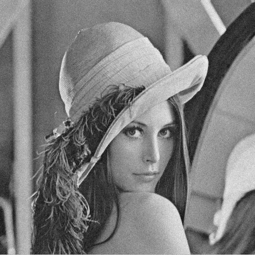
原圖

Noise圖片